CAN-FD
The CAN FD protocol introduces an adjusted CAN frame to enable the extra data bytes and flexible data rates.
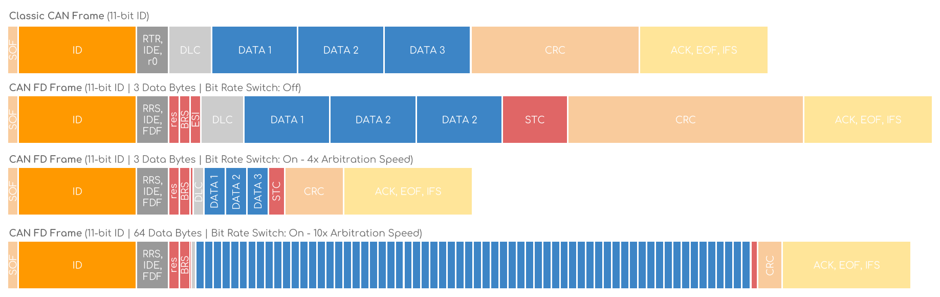
Below we compare an 11-bit classic CAN frame vs. an 11-bit CAN FD frame (29-bit is also supported):
Let’s run through the differences step-by-step:
RTR vs. RRS: The Remote Transmission Request (RTR) is used in classic CAN to switch between regular frames and remote request frames. In CAN FD, this functionality is disabled and the bit is renamed to Remote Request Substitution (RRS), always dominant (0)
r0 vs. FDF: In classic CAN, r0 is reserved and dominant (0). In CAN FD, it’s named FDF and recessive (1) to denote an FD frame.
After the r0/FDF bit, the CAN FD frame adds “3 new bits” vs. the classic CAN frame. Note that nodes that are not CAN FD capable may produce an error frame in response to the FDF bit and these 3 new bits.
res: This new reserved bit plays the same role as r0 - i.e. it may in the future be set to recessive (1) to denote a new protocol.
BRS: The Bit Rate Switch (BRS) can be dominant (0), meaning that the CAN FD frame payload is sent at the arbitration rate (i.e. up to max 1 Mbit/s). Setting it to recessive (1) means that the payload is sent at a higher bit rate (in practice up to 5 Mbit/s).
ESI: The Error Status Indicator (ESI) bit is by default dominant (0), i.e.‘error active’. If the transmitter becomes ‘error passive’ it’ll be recessive (1) to indicate a failure in the system. In practice, this helps identify errors early on, improving e.g. safety.

DLC: Like in classic CAN, the CAN FD DLC is 4 bits and denotes the number of data bytes in the frame. The above table shows how the two protocols use the DLC consistently up to 8 data bytes. To maintain a 4 bit DLC, CAN FD uses the remaining 7 values from 9 to 15 to denote the number of data bytes used (12, 16, 20, 24, 32, 48, 64).

SBC: The Stuff Bit Count (SBC) precedes the CRC and consists of 3 graycoded bits and a parity bit. It is added in CAN FD to help improve communication reliability. Note that the SBC is surrounded by 2 fixed stuff bits.
CRC: The Cyclic Redundancy Check (CRC) is 15 bit in the classic CAN, while in CAN FD it’s 17 bits (for up to 16 data bytes) or 21 bits (for 20-64 data bytes). In classic CAN, there can be 0-3 stuff bits in the CRC, while in CAN FD there are always 4 fixed stuff bits, again to improve communication reliability.
ACK: The data phase (aka payload) of the CAN FD frame stops at the ACK bit, which also marks the end of the potentially increased bit rate.
OVERHEAD & DATA EFFICIENCY OF CAN-FD VS. CAN
As evident, the added functionality of CAN FD adds a lot of extra bits vs. classic CAN - how can this lead to less overhead?
The answer is that it doesn’t - see the below visualization of classic CAN vs. CAN FD for 3 data bytes. In fact, the efficiency of CAN FD does not exceed classic CAN until crossing 8 data bytes. However, by moving towards 64 data bytes, the efficiency can go from ~50% up towards ~90% (more on this below).